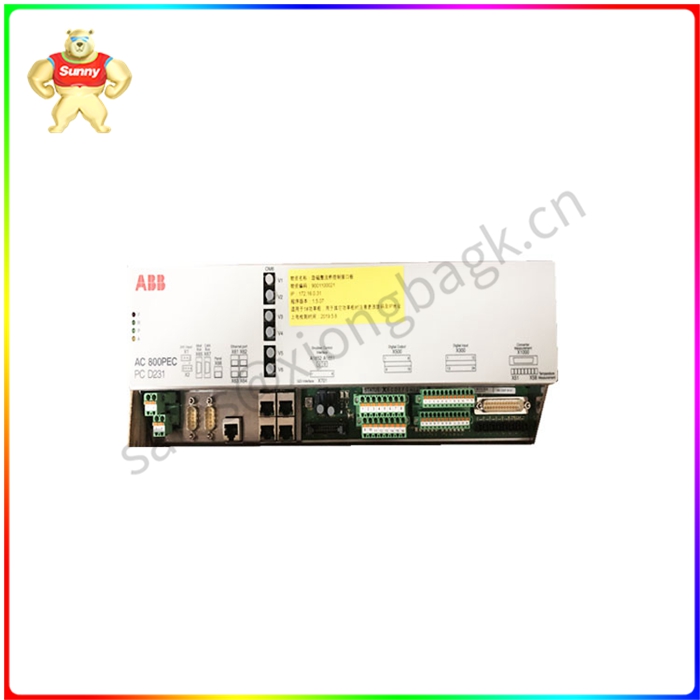

PCD231B101 励磁控制系统控制器
主回路的组成和功能
装置主回路完成整流和灭磁两大功能,系统采用三相全控桥可控硅整流电路,向同步电动机转子绕组提供直流励磁电流。灭磁回路由可控硅7、8KGZ与二极管GZ反并联组成,实际上组成为一个大功率电子开关,完成同步电动机在异步起动过程中串入起动电阻,起动结束后自动切除,保证同步电动机在异步起动期间,转子励磁绕组既不开路也不短路,从而避免励磁绕组承受过电压和过电流。
励磁装置控制部分:
系统控制部分包括S7200PLC、Pro-face触摸屏、KGLF-2型微机励磁控制器三部分组成。 PLC主要完成继电回路逻辑控制工作方式切换、运行时PI调节以及对外通讯等工作,Pro-face触摸屏主要完成系统参数设置和运行时故障、工作时间、设定运行参数信息查询,Pro-face触摸屏具有励磁电流和励磁电压录波曲线信息查看。
KGLF-2型励磁控制器里由主机MC87C51和副机AT89C51单片机组成。励磁控制器主要完成频率测量及投励、脉冲形成、故障检测及处理。
1转子感应电压频率的测量
同步电动机起动时, 转子感应电压的频率随着转速的上升逐渐下降,同步电动机一旦起动, 单片机就立即检测转子感应半个周波的时间, 从20ms开始, 数码管记“9”,中间每增加20ms, 数码减1, 到200ms时数码管显示“0”。同步电动机在异步起动过程中,当转子转速达到同步转速的90%时,转子感应电压的频率5Hz,周期0.2s,半周时间为100ms,计算机一旦检测到该值,立即投全压。投全压后,电动机的转速将继续上升,当转速增加到同步转速的95%时,转子感应电压的频率为2.5Hz,周期为0.4s,半周时间为200ms ,计算机检测到此值,迅速进入整流程序, 输出脉冲, 装置投入励磁, 同时接通投励工作指示, 关掉低压灭磁并开放失磁保护和失步保护等。
2脉冲形成
同步信号Ta、W3 提供正偏移,及励磁调节器的输出信号Uk,三者通过运算放大器综合处理后作为单片机外部中断请求INT0的输入信号,当INT0从1变0时, 单片机接受中断, 立即发出第 一组脉冲去触发1# 可控硅,同时给6#可控硅补一个脉冲。以后每间隔60°发下一组脉冲, 触发相应的可控硅,直至一个周期六组脉冲发完, 再等待下一次中断。改变Uk的大小就改变了中断申请的时刻, 达到控制角的目的。 为了提高整流电压波形的对称度,系统还不断监测电网的频率,随时对60°定时进行修正,确保整流电压波形对称,这样产生的脉冲精度高, 无需外部调整, 且稳定可靠。

PCD231B101 励磁控制系统控制器
Composition and function of the main loop
The main circuit of the device performs two functions of rectification and demagnetization. The system adopts three-phase fully controlled bridge thyristor rectifier circuit to provide DC excitation current to the rotor winding of synchronous motor. The degaussing circuit is composed of thyristor 7, 8KGZ and diode GZ in inverse parallel, in fact, it is composed of a high-power electronic switch to complete the synchronous motor in the asynchronous starting process into the starting resistance, and automatically cut out after the start, to ensure that the synchronous motor in the asynchronous starting period, the rotor excitation winding is neither open nor short circuit. Therefore, the excitation winding can avoid overvoltage and overcurrent.
Excitation device control part:
The control part of the system consists of S7200PLC, Pro-face touch screen and KGLF-2 microcomputer excitation controller. PLC mainly completes the switching of relay circuit logic control working mode, PI adjustment during operation and external communication, etc. Pro-face touch screen mainly completes the system parameter setting and operation fault, working time, set operation parameter information query, Pro-face touch screen has the excitation current and excitation voltage recording curve information view.
KGLF-2 excitation controller is composed of MC87C51 and AT89C51 microcontroller. Excitation controller mainly completes frequency measurement and excitation, pulse formation, fault detection and processing.
1 Measurement of rotor induced voltage frequency
When the synchronous motor starts, the frequency of the rotor induced voltage gradually decreases with the rise of the speed, once the synchronous motor starts, the MCU immediately detects the rotor induced half cycle time, starting from 20ms, the digital tube is marked "9", every 20ms in the middle, the number is reduced by 1, to 200ms when the digital tube shows "0". Synchronous motor in the asynchronous starting process, when the rotor speed reaches 90% of the synchronous speed, the rotor induced voltage frequency of 5Hz, period 0.2s, half week time is 100ms, once the computer detects the value, immediately throw the full voltage. After full voltage, the motor speed will continue to rise. When the speed increases to 95% of the synchronous speed, the rotor induced voltage frequency is 2.5Hz, the period is 0.4s, and the half cycle time is 200ms, which is detected by the computer. Quickly enter the rectification procedure, output the pulse, the device is put into excitation, at the same time, turn on the excitation work instruction, turn off the low voltage magnetic field and open the loss of magnetic protection and out-of-step protection.
2 Pulse formation
The synchronization signals Ta and W3 provide positive offset, and the output signal Uk of the excitation regulator. After comprehensive processing by the operational amplifier, the three are used as the input signal of the MCU external interrupt request INT0. When INT0 changes from 1 to 0, the MCU accepts the interrupt and immediately sends out the first set of pulses to trigger the 1# thyristor, and at the same time gives a pulse to the 6# thyristor. After every 60° interval, the next set of pulses are sent, triggering the corresponding thyristor, until the six sets of pulses are sent in a cycle, and then wait for the next interruption. Changing the size of Uk changes the interrupt request time to control the corner. In order to improve the symmetry of the rectifier voltage waveform, the system also continuously monitors the frequency of the power grid, and corrects the 60° timing at any time to ensure that the rectifier voltage waveform is symmetrical, so that the pulse generated is high precision, no external adjustment is required, and is stable and reliable.
PCD231B101 励磁控制系统控制器
| Reliance | DSPM-2A S-D4041A |
| ABB | SDCS-CON-4 |
| EMERSON | A3120/022-000 |
| A-B | 2711P-T12C6D1 |
| Nordson | 1023189B02 47-0015-067D |
| A-B | 80026-044-06 |
| SAIA | PCD2.M110D162 |
| LAFERT | B7108P-03177 |
| TRIDENT | 5351S2 |


 QQ在线客服