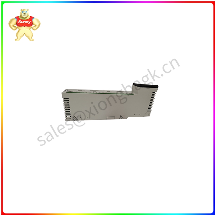
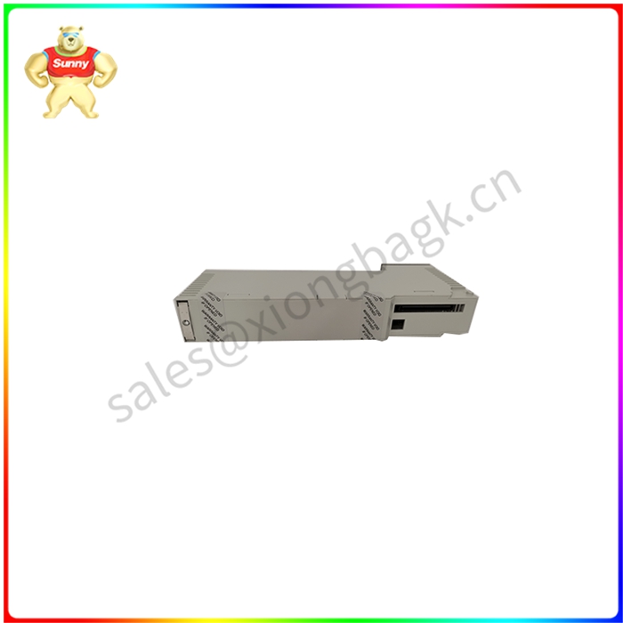
140ARI03010 模拟输入模块 总线通信进行中
140ARI03010配置中的现场接线端子板和模块外壳位于PCB卡槽的左右两侧,以接受键控引脚(见I/O模块图)。键控的目的是防止接线连接完成后将端子板插入错误的模块。用户可自行决定是否进行键控。
主键位于140ARI03010配置的右侧,标记为A至F(顶部和底部位置编码相同)。主键提供模块类别编码。主要代码已预定义(见下图)。辅助钥匙位于模块的左侧,标记为1至6。二级键控代码是用户可定义的,可用于识别模块类别中的模块个性,或其他独特的现场要求。为了支持键控,所有接受端子板的140ARI03010模块都带有12个可由客户安装的主键(模块和端子板各6个黄键)和6个辅键(模块和端子板各3个白键)。
为了实现用户可选的二级键控代码(旨在防止端子排与相同类型的I/O模块不匹配),在模块和端子排中提供了17个插槽位置,以支持各种编码方案。
此外(通过使用二级键控代码),用户可以使用每个代码的白键,将现场接线端子键入背板中安装模块的位置。
140ARI03010地图状态
这量子I/O映射菜单项允许您分配3x寄存器,该寄存器定义I/O映射模块状态可用的表的开始。您可以输入3x值,也可以输入0值(表示没有选择)。输入的值显示在量程I/O图顶部的摘要信息中。背板中的模块以8位字节报告状态(和故障)信息,因此,表中的一个字传达两个模块的状态信息


140ARI03010 模拟输入模块 总线通信进行中
The field terminal board and module housing in the 140ARI03010 configuration are located on the left and right sides of the PCB card slot to accept the keying pins (see I/O module diagram). The purpose of keying is to prevent the terminal board from being inserted into the wrong module after the wire connection is complete. Keying is at the discretion of the user.
The main keys are located to the right of the 140ARI03010 configuration and are labeled A to F(the top and bottom positions are coded the same). The primary key provides the module class code. The main code is predefined (see figure below). The auxiliary keys are located on the left side of the module and are marked 1 to 6. Secondary keying codes are user definable and can be used to identify module personalities within module categories, or other unique field requirements. To support keying, all 140ARI03010 modules that accept terminal boards come with 12 primary keys (6 yellow keys for each module and terminal board) and 6 secondary keys (3 white keys for each module and terminal board) that can be installed by the customer.
To enable user-optional secondary keying codes (designed to prevent the terminal block from mismatching with the same type of I/O module), 17 slot positions are provided in the module and terminal block to support various coding schemes.
In addition (by using secondary keying codes), the user can use the white key of each code to type the field terminal into the location of the mounting module in the backplane.
140ARI03010 Map status
This quantum I/O mapping menu item allows you to allocate 3x register, which defines the start of the table available for the I/O mapping module state. You can enter a 3x value or a 0 value (indicating no selection). The entered values are displayed in the summary information at the top of the range I/O diagram. Modules in the backplane report status (and failure) information in 8-bit bytes, so one word in the table communicates status information for both modules
140ARI03010 模拟输入模块 总线通信进行中
| TRICONEX | 3511 |
| kongsberg | RCU502 |
| AB | 6186M15PT |
| EPRO | PR6424/013-030+CON021 |
| TRICONEX | MP3101S2 |
| Honeywell | 51402497-200 |
| ABB | DSAO120A 3BSE018293R1 |


 QQ在线客服